As a kid in 1998, I was given an old IBM PS/2 to play games on. It only had one problem: with no USB (naturally) and no optical drive in it, I could not add more games to the hard drive, since the floppy drive didn’t work properly. However, I was curious to see an orange light come on, instead of the more familiar green, and there was “2.88” written on its eject button. What sorcery was that?
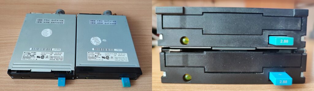 Mitsubishi MF356F-899MF, one of the types of 2.88MB drives used in later IBM PS/2 variants.
The one to the left has a partially broken faceplate and a replacement 34-pin connector.
Eventually, I got the non-working 2.88MB floppy drive swapped for a “normal” one, never to see it again. At that time I used to frequent a local net cafe with a sack of diskettes, one of them containing WINRAR and a file splitter utility, being very picky what to download – as I knew I would fit a maximum of some 1.38MB on 1 floppy, so I didn’t even use the “self extracting” archiver option to save space. Naturally, having the option to format a floppy to hold two times as much data, meant more games and stuff in one visit… As I found out later, it wouldn’t be that simple. 
A year later or so I got 56k dialup. Yay! An internet connection about as fast as a floppy disk transfer. With sometimes losing sync during handshaking, and a darn loud screeeeeech when it happened…
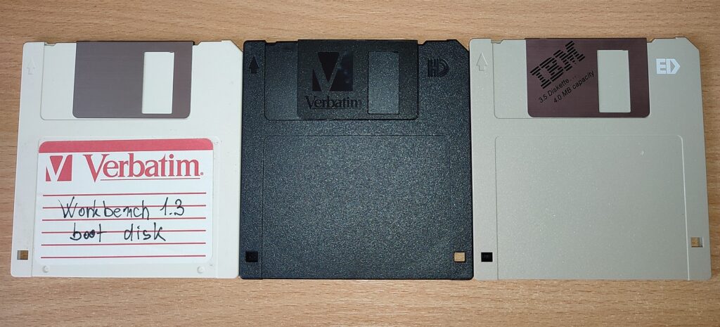 Double-, high- and extended-density 3.5″ media
Fast forward 20 years (actually, a lil bit more than twenty) to the era of cloud data storage, when I made an open source project that can work with these old dinosaurs over USB – making use of old chips, blown away with a hot air gun from an expansion card, with a nowadays popular platform that hobbyists know about.
In other words, this is the same MegaFDC Arduino software project documented above; with the board having in place of a DP8473 FDC, it has been wired up to work with an Intel 82077-compatible controller, such as the National Semiconductor/NSC PC8477. As in the original project above, it will also work with 8-inch “boat anchor” drives too, although the FM recording mode is not guaranteed per NSC datasheet (and explicitly mentioned as unsupported for the application of Intel 82077AA). However, both of these controllers can be used in conjunction with such an oddity that a 2.88M drive is…
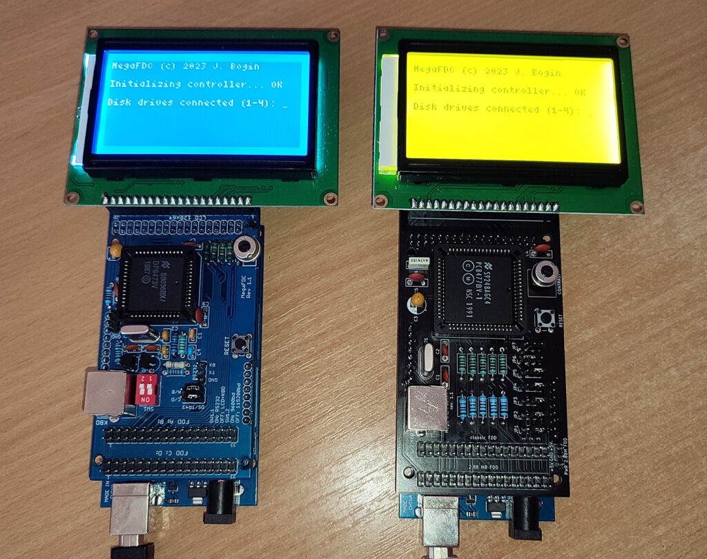 MegaFDC with a DP8473 on the left; PC8477 (2.88MB capable board) on the right.
PCB available here. It was about time I moved from dead-bug experiments soldered on un-etched, island-cut copper boards
A 3.5″ extended density floppy had twice the number of sectors per track than a regular high density diskette. To accomplish this, the magnetic media used a different oxide material and adjusted inter-sector gaps in what was known as the perpendicular recording mode (more on that in the Intel Technical Note AP-358 – Intel 82077SL for Super Dense Floppies), and a doubled data rate of 1 Mbps, instead of 500kbps used in high density diskettes.
A DP8473 used in the original project could be programmed for a data rate of 1Mbps, so that were my first experiments. However, only a six microsecond time window was allowed to service the interrupt handler – leading to data overruns if not satisfied. Since approx. 6us was just the actual initialization (Arduino register overhead) before passing control to the ISR written in C, I made the ISR in “naked assembly” to decrease spent time and also overclocked the Mega2560 from 16 to 20MHz. This involved replacing the ceramic resonator with a crystal, building a new STK500v2 bootloader (plus a new entry to boards.txt, with a different f_cpu) and flashing it over the ICSP pinheader, using another Arduino as an ISP programmer.
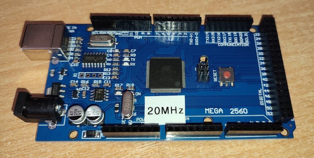 Mega2560 overclocked to 20MHz to decrease time spent in ISR written in assembly.
At 22.1184MHz, sketches failed to verify after uploading; at 24 MHz the board was no longer responding (crystal oscillator still working though).
The final version of the 2.88MB floppy access works with a non-modified, vanilla 16MHz Mega2560 – a FIFO buffer is used to hold the data. The ISR in ASM was thus scrapped.
After that experiment, the DP8473 used in the original project was no longer resulting into Data Overrun errors. However, the 1Mbps transfer rate was only one of the required preconditions – the chip did not support the “perpendicular recording mode” command, used to adjust gap sizes internally for the read and write commands; as such, these diskettes would not work with a DP8473. So I made a second MegaFDC board, equipped with an NSC PC8477 (itself an improved variant of the Intel 82077AA), as an example that the MegaFDC can be used with different controllers.
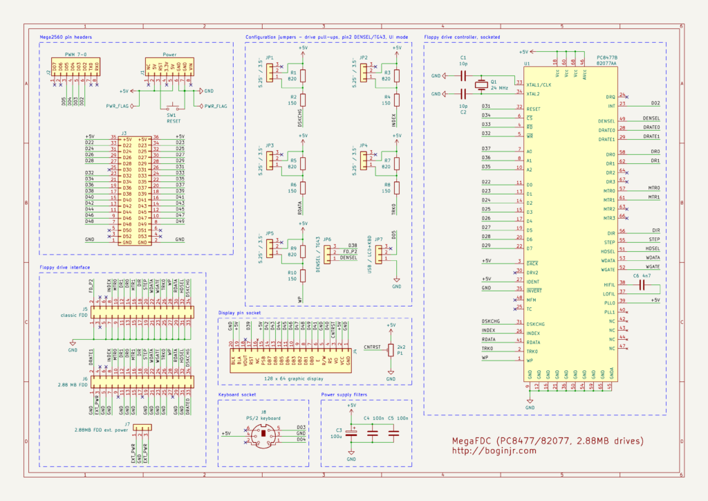 MegaFDC with an 82077AA/PC8477 and 2.88MB drives support
Compared to the previous variant with the DP8473, this board is also an Arduino “shield”, and is set up to be used with either a PC8477 controller, or an 82077AA in 68-pin PLCC can be dropped in without modification. The RS232 level shifter and the baud rate switch to 9600bps are omitted here for simplicity, but since the same software package is used, they can be put back if desired.
A second pinheader in the previous MegaFDC project was used to connect floppy drives C: and D:. In here, it is reserved to connect to a 3.5″ 2.88MB drive, such as the Mitsubishi above, since they have a slightly different pinout to classic PC floppy disk drives. Also, 5 switchable pull-ups are introduced, to switch between 150 ohms and 1K on the drive output lines (RDATA, WPROT, TRK00, INDEX and DSKCHG). This is because a 3.5″ 2.88MB drive will not sink enough current if classic 150 ohm terminators are used, and thus will not read anything at all. Ask me how I know!
The jumper to switch between pin 2 behavior on the “classic FDD” connector – i.e. between DENSEL and TG43 for 8-inch drive support – is kept in, also the UI switch between USB only, or through keyboard and display.
An external three-pin power connector, with +5 volts on sides and GND in the center, is provided for a 2.88MB drive. These do not have a separate power connector, +5 volts is supplied through the data cable on pin 3. Be careful with the cable orientation
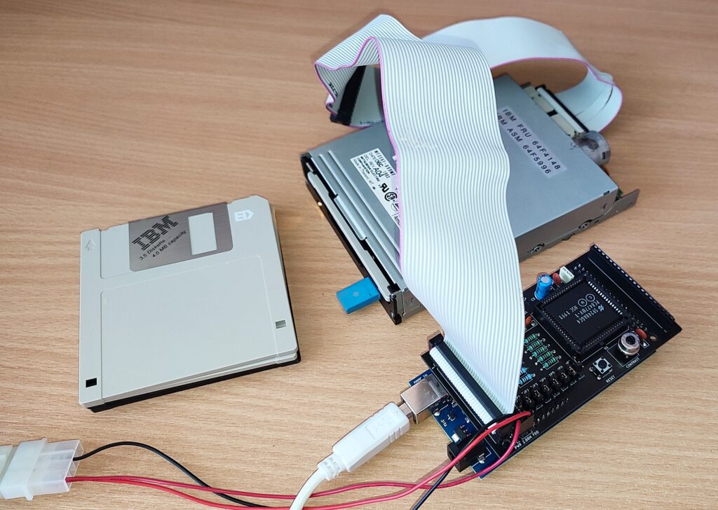 In action with the Mitsubishi MF356F drive.
All three disk densities (720K DD, 1.44MB HD and 2.88MB ED) can be used in MegaFDC this way.
Fun fact: a good 1.44MB floppy will pass format with verify to 2.88MB with a setup like this, as MegaFDC doesn’t care about the disk density hole.
Of course, reliable data storage is not guaranteed.
As we know, 2.88MB ED floppy drives didn’t catch on… what a surprise. As such, their interface was not standardized: the Mitsubishi drive has a similar pinout to a vanilla PC floppy drive, but it cannot be connected directly to a PC FDC bus (other than PS/2) if low pullup resistors are in use, as mentioned, plus there’s a different way of signaling what kind of disk density is in use.
For example: a 5.25″ floppy drive in a PC normally expects pin 2 (density select, DENSEL) to be active high for high density disks (and low for double density disks). For 3.5″ HD drives this is the other way around, but they mostly do not care about this signal, and determine disk density based on the presence of a hole in the bottom right of the disk. A 2.88MB drive like this, has 2 density select lines: one on pin 33 (connected to DRATE0) normally grounded in a PC, and the other on pin 2 (DRATE1, DENSEL in a PC), allowing for 4 combinations, one of them reserved.
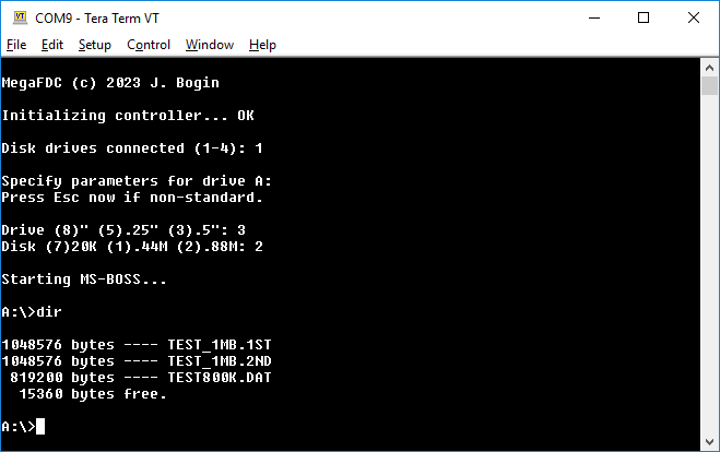 Directory listing showing 2.8MB occupied on disk
In other drives or brands, this behavior, or even the pinout as whole, might differ. Some 2.88MB drives also provide media type IDs or “security command” signals, to prevent a floppy from being ejected etc.
Apart from pin 3, which is normally left unconnected for a classic PC diskette drive, or used as a “key” to prevent inserting the cable the other way around, for the Mitsubishi here it provides +5Vcc – so you do not want to connect this to a drive that has all odd pins tied to GND. The drive doesn’t require +12V since it’s a 3.5″.
To use a drive like this in a normal old PC, a short floppy cable is to be used, with +5Vcc on pin 3, and each of the pins 8,26,28,30,34 need to read at least 1Kohms against +5Vcc. Pin 33 will be grounded always, allowing for the PC DENSEL on pin2 to choose between 720K and 1.44M operation. The drive is internally jumpered for DS1, so an A: goes after the cable twist as usual.
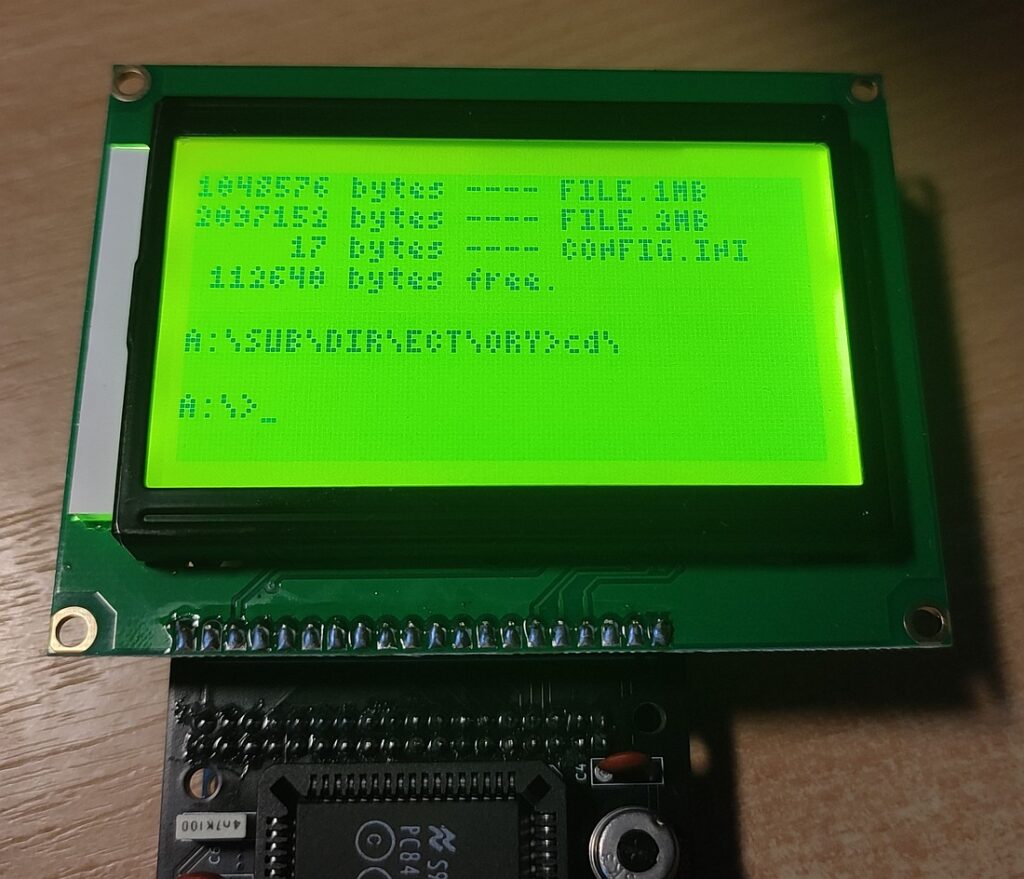 Regular 1.44MB HD media formatted to 3.12MB in a 2.88 drive
(82 tracks, 39 spt, sector/format gap 0x10/0x28, 1Mbps perpendicular mode)
Also, previous revisions of MegaFDC offered the 2.88MB floppy drive selection for all occurences. The software now checks if the floppy controller chip supports a CONFIGURE command to set up a FIFO buffer, used to hold the disk data until serviced by an ISR, to offer a 1Mbps data rate during setup, and also a check is used if the MODE command can be used to enable perpendicular recording. For MegaFDC to offer the 2.88MB diskette mode through software, both the 1Mbps data rate and the perpendicular mode need to be supported by the FDC, otherwise just the 720K and 1.44M options are supplied. In all other cases, the functionality is just the same.
Using the Advanced setup of MegaFDC, invoked by pressing Escape during choosing of drive type, you’re free to experiment with a 1Mbps data rate by itself, and/or perpendicular recording itself, regardless of the media geometry configured – if the controller supports these two modes.
And that’s about the size of it! Here’s the 2.88MB setup in action:


